Impact test
letzte Bearbeitung: 21.08.2023 von: Oluschinski
| Ein Service der |
|---|

|
| Polymer Service GmbH Merseburg |
| Tel.: +49 3461 30889-50 E-Mail: info@psm-merseburg.de Web: https://www.psm-merseburg.de |
| Unser Weiterbildungsangebot: https://www.psm-merseburg.de/weiterbildung |
| PSM bei Wikipedia: https://de.wikipedia.org/wiki/Polymer Service Merseburg |
impact test
Charpy impact test
In 1898, Russel introduced a pendulum hammer as a test device for impact testing. However, this type of experimental test is now not associated with the name Russel, but with that of Charpy, G. A. A., which is the way in which Charpy used this method for impact testing of metallic materials from 1901 onwards. In 1904, Charpy proposed the integral impact energy as a toughness value, which he had determined by means of his known arrangement. Although 100 years have passed since the introduction of the Charpy test, the Charpy impact strength is still one of the most widespread methods in industrial testing practice, but this method has a legitimate field of application only in quality assurance due to numerous formal deficiencies.
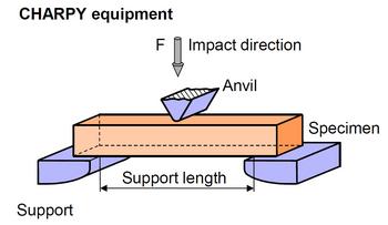
The Charpy impact test is standardized according to ISO 179 and is used for the assessment of the toughness of plastics under impact bend loading using unnotched test specimens. In the Charpy arrangement, the test specimen is positioned on two supports and loaded with an impact in the middle by a pendulum hammer of a pendulum device (see Fig. 1).
The prismatic test specimens must be produced according to the corresponding molding mass standard and can be produced directly by means of injection molding or from pressed or cast plates. The test specimens type 1 (see table 1), which are mainly used for thermoplastics, can be taken from multi-purpose test specimens according to ISO 3167 type A. The test specimens type 2 and 3 are only used for composite materials with interlaminar shear fracture, for example, long-fiber reinforced plastics.
| Fig. 1: | Schematic representation of the Charpy arrangement for carrying out impact bending tests |
The fracture energy required for the destruction of the test specimens with defined dimensions (see table 1) is determined with the pendulum device. The gravitational force acts as a driving force. The measuring principle of a pendulum impact device is based on the determination of the difference between the fall angle and the climbing angle, which is determined by the energy loss of the pendulum hammer by the fracture energy on the test specimen.
| Length l (mm) | Width b (mm) | Thickness h (mm) | Support span L (mm) | |
|---|---|---|---|---|
| Type 1 | 80 ± 2 | 10,0 ± 0,2 | 4,0 ± 0,2 | 62 |
| Type 2 | 25 h | 10 or 15 | 3 | 20 h |
| Type 3 | (11 or 13) h | 10 or 15 | 3 | (6 or 8) h |
The calculation of the impact strength (Charpy) is carried out according to the following equation.
with
| Wc | Impact energy |
References
- Russel, S. B. (1898): Experiments with a New Machine for Testing Materials by Impact. American Society of Civil Engineers 39/826, 237–250 [Reprint: Siewert, T. A., Manahan S. (Eds.) (2000): The Pendulum Impact Testing: A Century of Progress. ASTM STP 1380, 17–45]
- Charpy, G. A. A. (1901): Essay on the Metals Impact Bend Test of Notched Bars. [Reprint: Siewert, T. A., Manahan, S. (Eds.) (2000): The Pendulum Impact Testing: A Century of Progress. ASTM STP 1380]; Charpy, G. A. A. (1901): Note sur L’essai des metaux a la flexion par choc de barreaux entailles. Association internationale pour l’essai des materiaux. Congres de Budapest 1901 [also published in: Soc. Ing. Civ. de Francis. Juni 1901, 848–877]
- Charpy, G. A. A. (1904): Report on Impact Test of Metals. Proc. Intern. Association for Testing Materials, Vol. I, Report III
- Grellmann, W., Seidler, S. (Eds.): Polymer Testing. Carl Hanser Verlag, München (2022) 3. Edition, p. 143 (ISBN 978-1-56990-806-8; see under AMK-Library A 22)
- ISO 179-1 (2010-06): Plastics – Determination of Charpy Impact Properties – Part 1: Non-instrumented Impact Test
Dynstat impact test
The determination of the toughness properties by means of DYNSTAT arrangement is preferably used when only small amounts of material are available (e.g. during component testing). In DIN 53435, the impact strength an on non-notched test specimens in the impact bend arrangement (DS – G) is determined according to the following equation:
DYNSTAT impact strength:
with
| An | the impact energy absorbed by the test specimen |
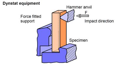
Fig. 2 schematically shows the impact bend arrangement of an unnotched test specimen.
| Fig. 2: | Impact bend arrangement DS – G for determining the toughness using the DYNSTAT arrangement |
The pendulum hammer energies possible for the test are 0.2 J, 0.5 J, 1.0 J and 2.0 J at an impact velocity of the pendulum hammer of 2.2 m/s. The test specimens are machined from the molded part (finished part). All surfaces and edges must not be damage free when viewing with the bar eyes. If necessary, scoring in the longitudinal direction caused by grinding (grain size 220 or finer) followed by polishing must be eliminated.
The dimensions of the rectangular cross section of the notched test specimens are:
| Length l | = | (15 ± 1) mm |
| Width b | = | (10 ± 0,5) mm |
| Thickness h | = | 1,2 – 4,5 mm |
The test specimen is inserted in a non-positive manner, the insertion length being lE (5,5 ± 0,1) mm.
'Reference
- DIN 53435 (2018-09): Testing of Plastics – Bending Test and Impact Test on Dynstat-Test Pieces
Izod impact test
The IZOD impact strength according to ISO 180 is determined both for rigid thermoplastic injection molding and extrusion molding compounds, thermosetting materials and thermotropic liquid-crystalline polymers as well as for filled and reinforced materials. In this case, the impact energy EC of an unnotched test specimen taken during the fracture is related to the initial cross-sectional area of the test specimen, according to the following equation:
| IZOD impact strength |
with
| Ec | impact energy | |
| h | thickness | |
| b | width |
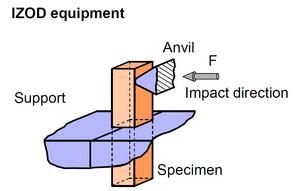
A schematic representation of the toughness test in the IZOD arrangement is shown in Fig. 3.
| Fig. 3: | Impact loading at IZOD arrangement |
The test specimens can be produced according to the corresponding molding mass standard or by pressing and injection molding or can be taken from multipurpose test specimens. The dimensions of the different test specimens are listed in the table.
The dimensions of the rectangular cross section of the notched test specimens are:
| Length l | = | (80 ± 2) mm |
| Width b | = | (10,0 ± 0,2) mm |
| Thickness h | = | (4,0 ± 0,2) mm |
Reference
- ISO 180 (2019-11): Plastics – Determination of Izod Impact Strength


